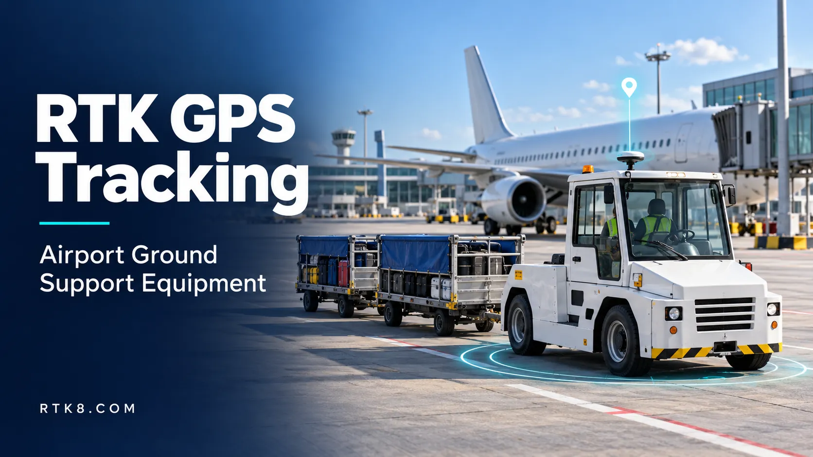
RTK GPS Tracker for Airport Ground Support Equipment: An OEM Deployment Guide
An airport operations team needs to locate a baggage tractor, identify available service vehicles and review equipment movements around aircraft stands.
A conventional fleet map can provide general visibility. Where operations require closer analysis of neighboring work areas, an RTK-capable tracking system may provide more useful positioning data under suitable reception and correction conditions.
An RTK GPS tracker for airport ground support equipment combines a compatible GNSS receiver, correction-data access, communication and a management platform. The project should define how position quality supports dispatch and reporting before selecting the hardware.
This article describes an OEM application to evaluate, rather than a claim that every tracking terminal is ready for airport deployment.
Which Equipment Could Benefit from RTK Tracking?
Ground support equipment includes powered vehicles and detachable assets with different installation needs.
| Equipment | Potential tracking purpose | Main design consideration |
|---|---|---|
| Baggage tractor | Dispatch, route review and work-area visits | Vehicle power, antenna placement and reporting rate |
| Ground power unit | Location and time spent at assigned areas | Powered versus disconnected operation |
| Airport service vehicle | Work-zone visibility and trip history | Coverage near buildings and aircraft |
| Towable service equipment | Asset availability and relocation history | Independent power and mounting |
| Baggage cart | Individual asset location | A tractor-mounted tracker does not identify each detached cart |
Define the tracked object precisely. Locating a tractor does not establish the positions of carts after they are disconnected.
Similarly, a vehicle’s presence near an aircraft stand does not by itself prove that a service task was completed.
Specify the Operational Question First
“Centimeter-level tracking” is too broad to serve as a complete project requirement.
A dispatch team may need to identify the nearest available tractor. An operations analyst may need to compare time spent in service areas. Another project may require repeatable position records along a defined outdoor route.
Translate these needs into measurable requirements:
- Which areas must be distinguishable?
- How recent must a displayed location be?
- What proportion of the operating route needs the target accuracy?
- How should the platform behave when position quality declines?
- Which events require an operator response?
These answers determine whether RTK is useful for the task and how the deployment should be tested.
Plan Correction Delivery Alongside Location Uploads
An RTK receiver needs compatible correction data to produce an RTK solution. Uploading vehicle coordinates to a platform is a separate function.
A device can remain connected to the tracking server while its correction stream is unavailable. The dashboard should therefore distinguish communication status from positioning status.
Depending on the selected receiver and network design, correction delivery may use a compatible network service or a local reference station.
Confirm:
- Correction formats supported by the receiver.
- Service availability across the operating area.
- Authentication and connection requirements.
- Correction-age reporting.
- Reconnection behavior.
- The position output when corrections are interrupted.
Do not assume that an active mobile connection establishes a valid RTK fix.
Choose the Position Reference Point
The location produced by a GNSS system relates to a defined reference point. That point may differ from the part of the vehicle the application needs to track.
An antenna mounted above the cab does not directly measure the front bumper, towing hitch or outer edge of a trailer.
For compatible integrated receivers, reference-point offsets can be configured. For example, u-blox’s ZED-F9R integration manual describes antenna and vehicle reference-point lever arms and explains why their configuration matters during vehicle motion. This is a receiver-specific capability, not a feature to assume in every RTK tracker.
For an airport equipment project, record:
- The antenna mounting location.
- The reference point represented by the output coordinates.
- Any configured offsets.
- The supported heading or attitude source.
- Whether attached equipment moves independently.
A fixed offset alone cannot describe the changing position of an articulated cart train during turns.
Evaluate Reception Around Aircraft and Buildings
Open outdoor areas can provide favorable GNSS conditions, but airport operations also include obstructions and reflective structures.
Test the installed equipment near terminal buildings, covered service areas and representative aircraft positions. Check antenna mounting stability and whether surrounding vehicle structures obstruct reception.
Results from an empty apron should not be treated as representative of every operating condition.
If the selected terminal includes inertial aiding or dead reckoning, verify its behavior separately. These capabilities may support continuity, but their performance during GNSS interruptions depends on the hardware, calibration, available inputs and outage duration.
The platform should expose degraded positioning instead of continuing to label every record as high precision.
Keep Position Quality in the Platform Record
Latitude and longitude alone are insufficient for evaluating a high-precision deployment.
Where supported, retain:
- Position acquisition time.
- Server receipt time.
- RTK fixed, float or other solution status.
- Receiver-estimated position uncertainty.
- Correction age.
- Positioning or fallback mode.
- Device power and communication status.
A receiver’s estimated uncertainty is useful diagnostic information, but it should not replace comparison with an independent reference during acceptance testing.
Maps and reports should distinguish recent high-quality positions from older or degraded records. Avoid presenting a smooth drawn route as evidence that all points met the accuracy target.
Use Work-Area Rules with Clear Limits
RTK data can support more detailed work-area analysis, but the quality of the digital boundaries also matters.
A carefully measured position compared with a poorly aligned map polygon may still produce an incorrect area assignment. Check that site boundaries and receiver coordinates use compatible reference information.
For operational reporting, define:
- Entry and exit conditions.
- Minimum dwell time.
- Treatment of boundary-adjacent positions.
- Behavior when positioning quality is inadequate.
- Handling of delayed uploads.
Describe reports according to what they establish. “Vehicle present in service area” is a location-based observation; “service completed” usually requires another source, such as a work-order update.
RTK tracking alone should not be presented as a certified collision-avoidance or automatic vehicle-control system.
Run a Representative Pilot
Start with a limited group of equipment types and the actual installation arrangement.
Include open areas, building edges, normal parking positions, turns, reversing and temporary correction interruptions.
Agree acceptance criteria before testing. Useful measures include:
| Measure | What it helps establish |
|---|---|
| Position error against an independent reference | Performance at the specified vehicle reference point |
| RTK fixed availability | How often a fixed solution is reported in each operating area |
| Recovery time | Behavior after loss of corrections or reception |
| End-to-end update delay | How quickly an acquired position reaches the operator |
| Work-area event accuracy | Whether entries and exits match reviewed movements |
| Missing-data behavior | Whether gaps remain visible in maps and reports |
Review results by operating area rather than relying only on one fleet-wide average. A strong result in open areas can conceal a recurring problem at a frequently used stand.
Define an OEM RTK Tracking Configuration
For an airport ground support equipment project, provide the vehicle models, electrical systems, mounting photographs, operating-area layout and required reporting interval.
Also specify the correction source, platform interface, position-quality fields and whether the system needs ignition status or additional equipment inputs.
Review the RTK8 product range as a starting point for discussing hardware. Confirm RTK receiver options, antenna arrangements, environmental suitability and integration functions for the selected configuration.
For related outdoor vehicle considerations, see the RTK GPS tracker guide for yard vehicles.
A useful deployment connects positioning performance with an operational decision: which equipment is available, where it was observed and how confidently that location can be used.
Frequently Asked Questions
Does RTK guarantee centimeter-level accuracy everywhere at an airport?
No. Performance depends on satellite reception, correction quality, installation and the operating environment. Validate the required accuracy in representative working areas.
Can one tracker locate a tractor and every connected baggage cart?
A tractor-mounted tracker identifies its configured reference point. Individually locating detached carts requires separate tracking or another suitable identification and positioning method.
Does an RTK fixed status prove the vehicle is inside the correct work area?
Not by itself. Boundary accuracy, coordinate alignment, reference-point selection and position freshness also affect the result.
Can an existing fleet platform accept RTK trackers?
Potentially, if it supports the device protocol or an appropriate integration. Confirm that it preserves position-quality information rather than accepting only coordinates.
What should buyers provide when requesting an OEM proposal?
Provide equipment types, quantity, deployment location, power supply, mounting constraints, required accuracy, reporting frequency, correction-service details and platform requirements.